


KFAS: Fanuc CNC Parts, Service, & Repair


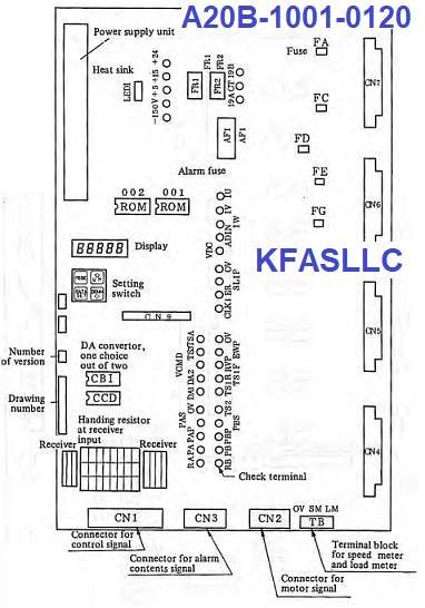
Fanuc A20B-1001-0120 A20B10010120
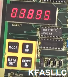
A20B-1001-0120 is equipped with LED display to indicate alarm condition.
Fanuc AC Spindle Unit Maintenance Manual B-53425E
Fanuc PCB A20B-1001-0120 can be found in A06B-6055 Spindle Units
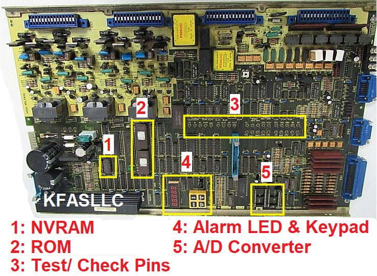
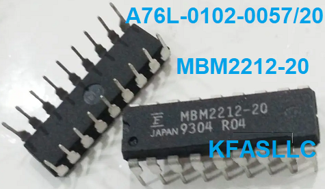
1: NVRAM: Fujitsu MBM2212-20 NON Volatile Random Access Memory
chip
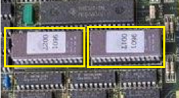
2: Spindle software ROM
3:
Test/ Check pins for various signals
4:
Alarm LED
display keypad for setting and viewing data
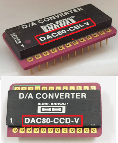
5: A/D converter for spindle command
signal (optional)
Parameter Description Summary (consult to manuals for more detail)
How
to view settings
A06B-6055-Hxx (A20B-1001-0120)
Maintenance Manual (B-53425E)
A06B-6059-Hxx (A20B-1003-0010) Maintenance Manual
(B-65015E)
(1) Press all 4 buttons ("MODE", "UP", "DOWN", and
"DATA SET") simultaneously until the 7-segment display reads "FFFFF" and then release the keys.
(2) Press and hold the "MODE" button and use the "UP" and "DOWN" buttons to go to the different parameter locations and record the values for each parameter.
F-00: Displays the motor revolution number (rpm)
F-01: MRDY (Machine Ready) signal is
Uses = 1
Not Used = 0
F-02: Speed Override is
Used = 1
Not Used = 0
F-03: Upper limit of Override
120% = 1
100% = 0
F-04: Type of Velocity Command
D/A Converter = 1
External Analog signal = 0
F-05: Spindle Motor Maximum Speed
5000~10000 = 0
6000~12000 = 1
~15000 = 2
~20000 = 3
F-06: Output limit pattern
No limit = 0
Limit of acce/dec = 1
Limit at rotation only = 2
Limit at all time = 3
F-07: Output Limit Value
0~100%
F-08: Delay time for motor power cutoff
0~255
Delay time = setting value x 40m sec
F-09: Motor power supply shut off by
MRDY (Machine ready) signal
This function is used = 1
Function is NOT used = 0
F-10: Velocity offset for forward rotation command (SFR)
0~255 (standard setting = 128)
F-11: Velocity offset for reverse rotation command (SRV)
0~255 (standard setting = 128)
F-11: Velocity offset for reverse rotation command (SRV)
0~255 (standard setting = 128)
F-12: Deviation offset for spindle orientation command (ORCM)
0~255 (Standard 128)
F-13: Forward command Rotation adjustment (SFR)
0~255
F-14: Reverse command Rotation adjustment (SRV)
0~255
F-15: Rotation number when velocity command voltage is 10V
Rotation number = setting value x 100
F-16: Detection range of Speed arrival signal (SAR)
0~100 (standard setting =15)
F-17: Speed Detection Signal (SDT) detection range
0~100 (standard setting =3)
F-18: Torque limit value
0~100 (standard setting = 50)
F-19: Acceleration/ Deceleration time
0~255 (standard setting=10)
setting value = acce/dec time (sec) x 2
F-20: Limiting of regenerative Power
0~100 (standard setting=60)
F-21: HIGH Gear Velocity control phase compensation P
0~255 (standard setting=50)
F-22: LOW Gear Velocity control phase compensation P
0~255 (standard setting=50)
F-23: HIGH Gear Orientation Velocity control phase compensation P
0~255 (standard setting=100)
F-24: LOW Gear Orientation Velocity control phase compensation P
0~255 (standard setting=100)
F-25: HIGH Gear Velocity control phase compensation I
0~255 (standard setting=30)
F-26: LOW Gear Velocity control phase compensation I
0~255 (standard setting=30)
F-27: HIGH Gear ORIENTATION Velocity control phase compensation I
0~255 (standard setting=30)
F-28: LOW Gear ORIENTATION Velocity control phase compensation I
0~255 (standard setting=30)
F-29: Velocity detection offset
(Range: 0~255)
Adjust the setting so that check-pin
TS3 =0V when motor is stopped
F-30: Adjustment of motor revolution number display
Setting Range = 0~8191
Adjust so that actual motor revolution
matches display value on the drive unit
F-31: Torque limit signal usage for rigid tapping mode
0-1 (standard setting = 1)
F-32: Motor voltage at normal operation
0~100 (standard setting = 10)
F-33: Motor voltage at spindle orientation
0~100 (standard setting = 10)
F-34: Motor voltage at rigid tapping mode
0~100 (standard setting = 10)
F-35: Speed zero signal detection level (SST)
0~255 (standard setting = 75)


