


KFAS: Fanuc CNC Parts & Repair
![]()
![]()
Fanuc 16/ 18/ 21 Data Download/ Backup
Step 1: Set up your Personal Computer (PC) or laptop to receive data.
(click here for information on RS232 setup)
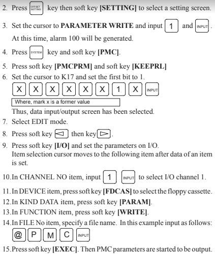
Step 2: Punch out NC Parameters as follow
Select EDIT mode.
Press "SYSTEM" key then press soft key [PARAM]
to display parameter screen.
Press soft key [(OPRT)], and soft key [=>].
Press soft key [PUNCH] and [EXEC], and the parameters are started to be
output.

Step 3: Punch out PMC Parameters as follow
Press "SYSTEM" key then press soft key [PMC].
Press soft key [PMCPRM], and soft key [KEEPRL].
Set Keeprelay K17 bit#1 = 1.
Press soft key [PUNCH] and [EXEC], and the parameters are started to be
output.
Select EDIT mode.
Press soft key [<=] then key [=>]
Press soft key [I/O] and set the parameters on I/O.
Set CHANNEL NO = 1.
Set DEVICE = FDCAS.
Set DATA KIND = [PARAM].
Set FUNCTION = [WRITE]
Press softkey [EXEC] to start output.
Step 4: Punch out Pitch Error as follow
Press "SYSTEM" key several time, then press soft key [PARAM], [=>]
and [PITCH].
Press soft key [OPRT] and [=>].
Press soft key [PUNCH] and [EXEC].

Make sure parameter no. 10 bit#4 = 0 (unprotect programs 9000 ~ 9999)
Select EDIT mode.
Select PROGRAM Memory screen.
Key in “O-9999”.
Press OUTPUT START.
Step 5: Punch out Offsets as follow
Select EDIT mode.
Press [OFFSET/SETTING] key then [OFFSET] soft key.
Press OUTPUT START.

Step 6: Punch out Macro Variables as follow
Macro variables (#500 to #999) can be output.
Select EDIT mode.
Press [OFFSET/SETTING] key.
Press [=>] key and softkey [MACRO]
Press soft key [OPRT] and then [=>] key.
Press soft key [PUNCH] and [EXEC], then variables are output.

For Channel 3, see Parameter Manual, Fanuc #62450E, section 4.2 (5).
Parameter Description
Setting
0020 I/O Channel
0 or 1 = Chan. 1, 2=2
0100.1 Tape Vertical Check – all channels
0 = No TV Check
0100.3 EOB format in ISO code – all
chan. 1 = CR, LF, LF (0 = LF)
0100.5 DNC Handshake method – all chan
1 = DC3 when buffer full
0100.7 Treatment of Null code – all
chan. 1 = Ignore Nulls (0 = alarm)
0101.0 Stop Bits – Channel 0
0 = 1, 1 = 2 stop bits
0101.3 ISO or ASCII Input code – Chan. 0
0 = Auto-select (1 = ASCII)
0101.7 Feed output – Channel 0
1 = no feed (0 = feed output)
0102 Device Type – Channel 0
0 = RS232C with DC codes
0103 Baud Rate – Channel 0
10=4800,11=9600,12=19200
0111-0113 Same as 0101-0103 but for I/O Channel 1
0121-0123 Same as 0101-0103 but for I/O Channel 2
Fanuc
16/ 18/ 21 Data Upload
If the control memory is corrupted, star by initializing the entire memory
Power On holding RESET & DELETE with Write Protect Key off
NC Parameters
EDIT mode,
Protect key off;
SYSTEM [PARAM] [OPTR] [>] [READ] [EXEC]
Power the CNC off & back on after upload finishes.
Alarm 300 is normal at this stage if Absolute Pulse Coders exist.
Pitch Error Compensation
EDIT mode;
SYSTEM [>] [PITCH] [OPTR] [>] [READ] [EXEC]
All Programs
EDIT mode; Set parameter 3202#4 & #0 = 0;
PRGRM [OPTR] [>] [READ] [EXEC]
Offsets
EDIT mode;
OFFSET (or WORK ) [OPTR] [>] [READ] [EXEC]
PMC Data
The PMC communications settings are separate from the normal serial port settings.
Set them to match the settings for other serial communications so the PMC data can be easily backed up.
Restoring PMC Data
Get the computer ready to send the PMC data.
Make sure the CNC is ready to receive the PMC data
Select MDI mode and set PWE on (set
PRM 8000.0 to 1).
Note that some machine tools require that the Ladder be stopped before all the Data Tables can be loaded.
If so, press SYSTEM, PMC, RUN/STOP, >, STOP.
If the control has special options, such as a 5th axis table, you might need to power on holding “-“ & “.” and then select a boot without the ladder running.
Load the PMC data as follows:
Press OFFSET SETTING .
Select MDI mode and set PWE on (set PRM 8000.0 to 1).
Press SYSTEM [PMC] [PCMPRM] [KEEPRL].
Set K17 bit 1 to 1 (change no other bits in K17).
Select Edit mode. If required, set #K900 to 10.
Press [<] or [>] to find [I/O] .
For CHANNEL NO, input 1 .
For DEVICE, select FDCAS .
For DATA KIND, press PARAM .
For FUNCTION, press READ. For FILE NO, press 2.
Press [<] [SPEED] and check serial settings for [FDCAS].
Press [EXEC] and send PMC data from the computer.
Reset Absolute Pulse Encoders, if necessary.
Power on holding P & CAN
Manually home the machine.
If Alarm 300 persists, then:
Select MDI mode and set PWE on (set #8000.0 to 1).
Press SYSTEM [PARAM] . Set Parameter 1815#4 to 1 on all axes.
Reset PWE (PRM 8000.0 to 0) and power the control off & on.
Manually home the machine again. Set PWE.
Press SYSTEM [PARAM] . Set PRM 1815#4 to 1 on all axes.
For Relative Position, set PRM 3104#3 to 1.
Reset PWE. Press RESET .


![]() © Copyright
KFASLLC Houston, Texas, USA
© Copyright
KFASLLC Houston, Texas, USA