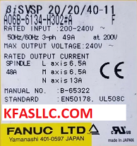
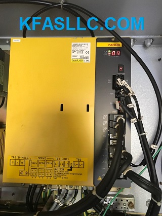
A06B-6134-H302#A or A06B6134H302
A06B-6134-H302#A - SERVO/SPINDLE MODULE MDL BiSVPM40/40/40-15 TYPE A
Repair available at $2300 including UPS GND shipping. 2 day turnaround, 12-month warranty.

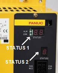
A06B-6134-H302 Series has two LED status indicators.

Alarm Code Description
Status 1
01 Motor
overheat (Alarm 9001, 7101)
02 Excessive
speed deviation (Alarm 9002, 7102)
03
DC link fuse is blown (Alarm 9003, 7103)
04 Open phase in the converter
main power supply
(Alarm 607, 9004, 7104)
6, 06 Temperature
sensor disconnected (Alarm 9006, 7106)
7, 07 Excessive
speed (Alarm 9007, 7107)
9, 09 Main
circuit overload/IPM overheat (Alarm 9009, 7109)
11 Converter:
DC link overvoltage (Alarm 439, 9011, 7111)
12 IPM alarm
(Alarm 9012, 7112)
18 Program
sum check error (Alarm 750)
19 Excessive
offset of the phase
U current detection circuit (Alarm
750)
20 Excessive
offset of the phase
V
current detection circuit (Alarm 750)
21 Position
sensor polarity setting
is
incorrect (Alarm 9021, 7121)
24 Serial
transfer data error (Alarm 749)
27 Position
coder disconnected (Alarm 9027, 7127)
29 Short-period
overload (Alarm 9029, 7129)
30 Overcurrent
in the converter input
circuit
(Alarm 437, 9030, 7130)
31 Motor
lock alarm (Alarm 9031, 7131)
32 Serial
communication LSI RAM
error
(Alarm 9032, 7132)
33 Converter:
DC link precharge
failure
(Alarm 442, 9033, 7133)
34 Parameter
data out of the allowable
range (Alarm 9034, 7134)
35 Gear
ratio parameter error (Alarm 9035, 7135)
36 Error
counter overflow (Alarm 9036, 7136)
37 Speed
detector parameter error (Alarm 9037, 7137)
41 Position
coder one-rotation signal
detection
error (Alarm 9041, 7141)
42 Position
coder one-rotation signal
not
detected (Alarm 9042, 7142)
46 Position
sensor one-rotation signal
detection
error during thread cutting (Alarm 9046, 7146)
47 Position
coder signal error (Alarm 9047, 7147)
50 Excessive
speed command calculation value
during
spindle synchronization (Alarm 9050, 7150)
51 Converter:
DC link undervoltage (Alarm 433, 9051, 7151)
52 ITP
signal error I (Alarm 9052, 7152)
53 ITP
signal error II (Alarm 9053, 7153)
54 Current
overload alarm (Alarm 9054, 7154)
58 Converter:
main circuit overload (Alarm 431, 9058, 7158)
73 Motor
sensor disconnected (Alarm 9073, 7173)
75 CRC
test alarm (Alarm 9075, 7175)
79 Abnormal
initial test operation (Alarm 9079, 7179)
81 Motor
sensor one-rotation signal
detection error (Alarm 9081, 7181)
82 Motor
sensor one-rotation signal
not detected (Alarm 9082, 7182)
83 Motor
sensor signal error (Alarm 9083, 7183)
84 Spindle
sensor disconnected (Alarm 9084, 7184)
85 Spindle
sensor one-rotation signal
detection error (Alarm 9085, 7185)
86 Spindle
sensor one-rotation signal
not detected (Alarm 9086, 7186)
87 Spindle
sensor signal error (Alarm 9087, 7187)
A
Program ROM error (Alarm
749)
A1
Program ROM error (Alarm
749)
A2
Program ROM error (Alarm
749)
b0 Communication
error between
amplifier and module (Alarm 9010, 7198)
b1 Converter:
control power supply
low voltage (Alarm 432, 9111, 7198)
C0
Communication data alarm (Alarm
9120)
C1
Communication data alarm (Alarm
9120)
C2
Communication data alarm (Alarm
9120)

STATUS 2
Alarm Description
2
Inverter: control power supply
undervoltage
(Alarm 434)
5
Inverter: DC link undervoltage
(Alarm 435)
b Inverter: motor current alarm (L axis)
(Alarm 438)
C
Inverter: motor current alarm (M axis)
(Alarm 438)
d Inverter: motor current alarm (N axis)
(Alarm 438)
8. Inverter: IPM alarm (L axis)
(Alarm 449)
9. Inverter: IPM alarm (M axis)
(Alarm 449)
A. Inverter: IPM alarm (N axis)
(Alarm 449)
F
Inverter: radiator cooling fan stopped
(Alarm 601)
6 Inverter: overheat
(Alarm 602)
8.
Inverter: IPM alarm (OH) (L axis)
(Alarm 603)
9. Inverter: IPM alarm
(OH) (M axis) (Alarm 603)
A. Inverter: IPM alarm
(OH) (N axis) (Alarm 603)
P Amplifier and module
communication error (Alarm 604)
U
FSSB
communication error (COP10B)
A06B6134-H302#A B65325E Manual
βiSVSP A06B-6134-H203#A Advantages
● All-in-one packaged Servo Amplifier: (servo 3 axes + spindle 1 axis): Fewer cable wiring are achieved by all-in-one structure.
● Energy Saving: Power source regeneration returns the deceleration energy of the motor to the power source.
● Addition of 2nd FSSB connector: Easy connection of multiple βiSVSPs or additional amplifier.
● Gravity-axis drop prevention function at power failure: Tool and work of machine is protected from breakage at power failure by activating the
motor brake quickly using built-in power failure detection function.
● Cs contouring control: For spindle separated sensor, αi BZ sensor is
supported to Cs Contouring control in addition to αi Position coder.
βi SVPM3-11i TypeA
A06B-6134 -H302#A
A16B-2101-0024
A20B-2101-0013
A20B-2902-0670
Other βiSVSP Units:
A06B-6134-H201#A,
A06B-6134-H202#A,
A06B-6134-H203#A
A06B-6134-H201#C, A06B-6134-H202#C,
A06B-6134-H203#C
A06B-6134-H301#A, A06B-6134-H302#A,
A06B-6134-H303#A
A06B-6134-H301#C, A06B-6134-H302#C, A06B-6134-H303#C
