


KFAS: Fanuc CNC Parts & Repair
![]()
![]()
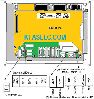
1) Alarm LED (red) indication
CORE ALM CCPU ALM 1 2 3 ALM | Meaning |
◇ □ ■ □ ◇ | Low battery voltage. The battery may be running out. |
◇ ■ ■ □ ◇ | Software detected an error and stopped the system. |
◇ □ □ ■ ◇ | Hardware detected a failure in the system. |
◇ ■ □ ■ ◇ | An alarm was issued with the servo card on the main board. |
◇ □ ■ ■ ◇ | An error was detected in the data of the SRAM on the FROM/SRAM module. The FROM/SRAM module may be faulty, the battery voltage may have dropped, or the main board may be faulty. |
◇ ■ ■ ■ ◇ | Abnormal power supply operation. The cause may be noise or the back panel (with power supply) failure. |
◇ ◇ ◇ ◇ ■ | The CPU card may be faulty. |
■ ◇ ◇ ◇ ◇ | Lights if there is an abnormal condition in the power supply on the main board. |
■: On □: Off ◇: Don’t care
(2) Ethernet (Embedded Ethernet) status LED
LED | Meaning |
LINK (green) | Turned on when a connection is made with the hub correctly |
COM (yellow) | Turned on when data is transferred |
(3) Ethernet (Multi-function Ethernet) status LED
In the following explanations, the LED lighting states are expressed as follows:
□: Off ■: On ☆: Blinking ◇: Don’t care
- LED display transition for STATUSF (during power-on)
LED display | Status | Meaning |
□ | Power-off | |
■ | Immediately after power-on | Initial state entered immediately after power-on. If the board is stopped in this condition, the cause is one of the following: → The CNC communication software may not be running normally. Check whether the communication software is installed properly. → The main board may be faulty. Replace the main board. |
☆ | Start completion | The board has started normally. |
- LED display for STATUSF (during normal operation)
LED display | Status | Meaning |
☆ | Normal status | The board is operating normally. |
- LED display for LCOM
LED display | Status | Meaning |
□ | Not connected to hub | The board is not connected to the hub properly. The LED stays off also when the power to the hub is off. Check whether the board is connected to the hub properly. |
■ | Connected to hub | The board is connected to the hub. |
☆ | Transmission/reception in progress | Data is being transmitted or received. |
- LED display for COL
LED display | Status | Meaning |
□ | Normal status | The board is operating normally. |
■ ☆ | Collision occurs. (Data collision occurs.) | The LED is on or blinks at short intervals when the Ethernet communication traffic (communication amount) is high or ambient noise is high. |
- LED display for HER
LED display | Status | Meaning |
□ | Normal status | The board is operating normally. |
■ | Error detected in the Ethernet circuit on the main board | The cause may be the faulty main board or a malfunction due to noise. |
☆ | Error detected in the software |
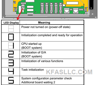
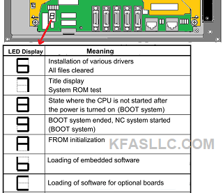
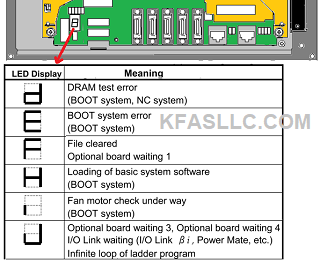
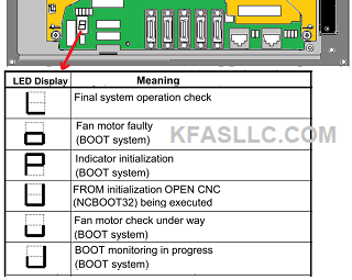
7-Segment LED