The status of the CNC can be monitored at all times. Press the DGNOS button to display the contents of the following diagnostics.
Fanuc Diagnostics 27, DGN 27
- PCS = 0
- The spindle position coder one revolution signal is off.
- PCS = 1
- The spindle position coder one revolution signal is on.
- ZRN4-1 = 0
- The pulse coder one revolution signal for 1 - 4 axis is off.
- ZRN4-1 = 1
- The pulse coder one revolution signal for 1 - 4 axis is on.
Fanuc Diagnostics 700, DGN 700
When these bits are equal to 1, they mean the following:
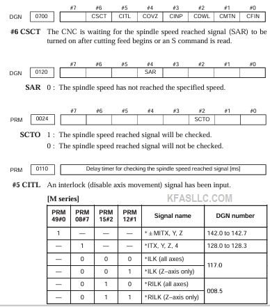
- CSCT
- The CNC is waiting for the spindle constant speed reached signal.
- CITL
- The interlock signal is on.
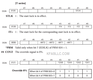
- COVZ
- The override is set to 0%.
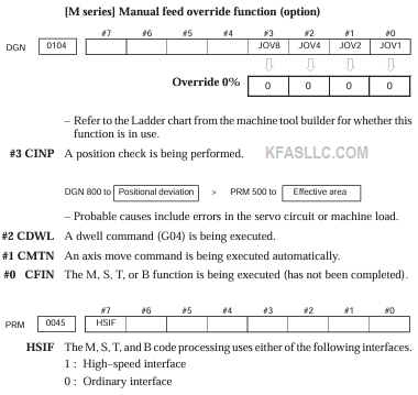
- CINP
- In-position check is being made.
- CDWL
- A dwell command is being executed.
- CMTN
- A tool movement command is being executed in automatic operation.
- CFIN
- The M, S, or T function is being executed.
Fanuc Diagnostics 701, DGN 701
When these bits are equal to 1, they mean the following:
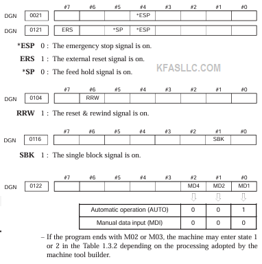
- CRST
- An emergency stop, external reset, reset and rewind, or reset button on the MDI panel is on.
- CTRD
- Data is being input through the RS232 interface.
- CTPU
- Data is being output through the RS232 interface.
Fanuc Diagnostics 702, DGN 702
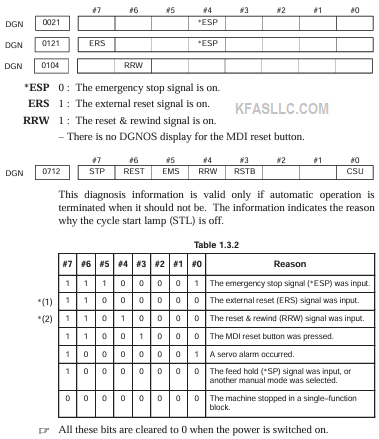
Fanuc Diagnostics 712, DGN 712
This diagnosis information is valid only if automatic operation is terminated when it should not be.
The information indicates the reason why the cycle start lamp (STL) is off.
All these bits are cleared to 0 when the power is switched on.
Fanuc Diagnostics 720, DGN 720
The details of servo alarm 4x4 are provided by the following diagnostics, in the order of X-axis through eighth axis. Example: 720 = X-axis, 721 = Y-axis, 722 = Z-axis, etc.
- OVL
- An overload alarm occurred. The thermal overload has operated. Either an overheat has occurred, the thermal device is defective, or the cable is broken. Check DGN 730 for motor or amplifier overheat.
- LV
- A low voltage alarm has occurred. Either the input voltage is low or the MCC is defective.
- OVC
- An overcurrent alarm has occurred. Check cutting conditions, motor current waveform, or digital servo parameter.
- HCAL
- An abnormal current alarm has occurred. Check the transistor module of the amplifier or the servo motor for a short.
- HVAL
- An overvoltage alarm has occurred. Check the input voltage, regenerative circuit, or servo motor.
- DCAL
- A regenerative discharge alarm has occurred. Check the connection of the discharge unit, condition of the discharge transistor, or amount of acceleration/deceleration.
- FBAL
- A disconnect of the pulse coder has occurred. A defective pulse coder or wire break may cause the alarm. Also check the parameter for setting of feedback type or cable shield.
- OFAL
- An overflow alarm has occurred. Incorrect digital servo parameter is the most likely cause.
Fanuc Diagnostics 730, DGN 730
Fanuc Diagnostics 760, DGN 760
The details of serial pulse coder alarms 319, 329, 339, and 349 are indicated by the following diagnostics.
- SFLG
- This is not an alarm bit. It is set to 1 when a serial pulse coder is used.
- CSAL
- A checksum alarm occurred. The serial pulse coder is defective.
- BLAL
- A low battery voltage alarm has occurred. Replace the battery.
- PHAL
- An abnormal phase data alarm has occurred. Either the pulse coder is defective or the cable is faulty.
- SCAL
- An abnormal rotation speed count alarm has occurred. The pulse coder is defective.
- BZAL
- A battery zero alarm has occurred. The pulse coder is powered for the first time. Check that the battery is properly connected and perform a zero return.
- CKAL
- A clock alarm occurred. Replace the pulse coder.
- SPHAL
- An abnormal software phase detect alarm has occurred. Either the pulse coder or cable is faulty.
Fanuc Diagnostics 800, DGN 800
Fanuc Diagnostics 820, DGN 820