

KFAS: Fanuc CNC Parts, Service, & Repair
Fanuc 16/ Fanuc 18 CNC Status Display and Details of Diagnostics
The status of the CNC can be monitored at all times.
If the control does not issue an alarm, press the DGNOS button to display the contents of the following diagnostics:
Display of status when a command is not apparently executed (DGN No. 000 – 015)
000: WATING FOR FIN SIGNAL
Meaning: M, S, T function is being executed
001: MOTION
Move command in automatic operation is being executed
002: DWELL
Dwell is being executed
003: IN–POSITION CHECK
In-position check is being performed
004: FEEDRATE OVERRIDE 0%
Override is set to 0%
005: INTERLOCK/ START–LOCK
Interlock is on.
006: SPINDLE SPEED ARRIVAL CHECK
Waiting for spindle speed arrival signal to turn on
010: PUNCHING
Data is being output via reader puncher interface
011: READING
Data is being input via reader puncher interface
012: WAITING FOR (UN) CLAMP
Waiting for index table clamp/unclamp indexing start or
after B axis is indexed
013: JOG FEEDRATE OVERRIDE 0%
Jog override switch is set at 0%
014: WAITING FOR RESET, ESP, RRW OFF
The emergency stop, external reset, reset & rewind or reset key is on.
015: EXTERNAL PROGRAM NUMBER SEARCH
External program number search is active.
016: BACKGROUND ACTIVE
Background Edit is being used.
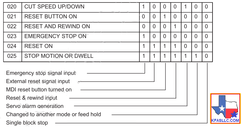
020: CUT SPEED UP/ DOWN
Set when emergency stop turns on or when servo alarm occurs
021: RESET BUTTON ON
Set when reset key turns on
022: RESET AND REWIND ON
Reset and rewind turned on
023: EMERGENCY STOP ON
Set when emergency stop is turned on
024: RESET ON
Set when external reset, emergency stop, reset
or reset & rewind key is on.
025: STOP MOTION OR DWELL
This status is set to 1 in the following cases.
(1) External reset is set to on.
(2) Reset & rewind is set to on.
(3) Emergency stop is set to on.
(4) Feed hold is set to on.
(5) The MDI panel reset key turned on.
(6) Switched to the manual mode (JOG/HANDLE/INC).
(7) Other alarm occurred.
Causes for CYCLE START LED is turned OFF
020 CUT SPEED UP/DOWN
021 RESET BUTTON ON
022 RESET AND REWIND ON
023 EMERGENCY STOP ON
024 RESET ON
025 STOP MOTION OR DWELL
(See below)
TH alarm statuses (No. 030, 031)
030: CHARACTER NUMBER TH DATA
The position of the character which turned TH alarm on is displayed
031: TH DATA
Read code of character which turned TH alarm on
The details of servo alarm 4x4 are provided by the following DGN,
No. 200 #7 #6
#5
#4 #3
#2 #1
#0
OVL LV OVC
HCAL HVAL DCAL FBAL OFAL
OVL: An overload alarm occurred.
The thermal overload has operated. Either an overheat has occurred, the thermal device has defected,
or the cable is broken.
LV: A low voltage alarm has occurred. Either the input voltage is low or the MCC is defective.
OVC: An overcurrent alarm has occurred. Please check cutting conditions, motor
current waveform or digital servo parameter.
HCAL: An abnormal current alarm has occurred. Please check the transistor module of
the amplifier or the servo motor for short.
HVAL: An overvoltage alarm has occurred. Please check the input voltage,
regenerative circuit or servo motor.
DCAL: A regenerative discharge alarm has occurred. Please check the connection of
the discharge unit, condition of discharge transistor or amount of acc/dec.
FBAL: A disconnect of the pulse coder has occurred. A defective pulse coder or wire
break may cause the alarm. Also, please check the parameter for setting of feedback type or shield of the cable.
OFAL: An overflow alarm has occurred. Incorrect parameter of the digital servo is most
possible cause.
No. 202 #7
#6 #5
#4 #3
#2 #1
#0
ALD
EXPC
ALDF EXPC
Details
OVL Alarm 1
0 Overheat detected at the Motor
0 0
Overheat detected at the amplifier
FBAL Alarm 1
0 Disconnect detected by hardware
0 0
Disconnect detected by software
1 1
Separate pulse coder detected by software.
The details of a serial pulse coder Alarm 319, 329, 339, 349 are indicated by the following diagnostics:
No. 203 #7
#6 #5
#4 #3
#2 #1
#0
SFLG CSAL BLAL PHAL SCAL
BZAL CKAL SPHAL
SFLG: This is not an alarm bit. It is set = 1 when serial pulsecoder is used.
CSAL: A check sum alarm occurred. The serial pulsecoder is defective.
BLAL: A low battery voltage alarm has occurred. Please replace the battery.
PHAL: An abnormal phase data alarm has occurred. Either the pulsecoder is defective
or the cable is faulty.
SCAL: An abnormal rotation speed count alarm has occurred. The pulsecoder is
defective.
BZAL: A battery zero alarm has occurred. The pulsecoder is powered for the first time.
Please check that the battery is properly connected and perform a zero return.
CKAL: A clock alarm occurred. Replace the pulsecoder.
SPHAL: An abnormal software phase detect alarm has occurred. Either the pulsecoder
or cable is faulty.
No. 300 SVERR
The amount of position following error is displayed.
No. 301 ABSMT
The machine position is displayed.


 © Copyright KFASLLC Houston, Texas, USA