


KFAS: Fanuc CNC Parts & Repair


Fanuc 10, 11 Alarm & Master Board Alarms
For FANUC System 10M, 10T, 10MA, 10TF, 10TTF, 11M, 11T, 11MA, 11TA, 11TF
A MDI connection failure
Check optical cable connection and connector of CRT/MDI unit.
Replace master PCB, MDI, PCB or optical fiber cable.
Check optical interface (MDI/CRT-Master PCB)
C MDI failure (incorrect ID number)
Check the type (9″, 14″ etc.) of CRT/MDI unit of the edition number of NC software.
Connection unit of operators panel or its connecting cable is defective.
Change MDI/CRT, PCB, Operators I/O PCB.
E System Error
Loose contact at connector of PCBs to master PCB.
Replace (1) Master PCB, (2) NC Software ROM, or (3) ROM board.
Check message at CRT.
No message at CRT- Clear all memory.
Wrong combination of ROM chips in system. Check option Data Sheet against S/W ROM set.
Wrong option parameters. May need extra RAM chips.
F Connection failure of connection unit or I/O cards D1-D3.
Check the optical fiber cable connections or these units and connectors.
Replace master PCB, connection unit, I/O cards D1-D3, or optical fiber cable.
Optical Interface ( I/O- Master PCB). IF01A PCB plugged into wrong slot in I/O rack.
Failed I/O module in I/O base unit.
H Different type of above mentioned unit (incorrect ID number)
Check the above inputs for their specified types or check the edition number of NC software.
Connection of Conn.Unit 2 or its connecting cable (flat) is defective. Conn.Unit 1-2.
J PC or interface converter does not function( while waiting for an answer).
Check if PMC ROM cassette, PMC RAM board or interface
converter is mounted on master PCB: or replace the above PCB.
Bad ladder or blank PMC cassette. Clear PMC RAM to correct.
L Waiting for PMC ready
Replace PMC ROM, PMC ROM cassette, or PMC Ram board.
Check the PMC program ( bug in program). Loose contact at I/O module (pos.etc) connector to back panel
b RAM check error. Transfer error through optical fiber cable.
Replace the master PCB or ROM/RAM board additional memory.
Wrong combination of ROM chips in system. Check Option Data Sheet against S/W ROM set.
Check alarm LED of the units connected by optical fiber cable.
Replace master PCB, MDI PCB, connection unit PCB, I/O unit, or optical fiber cable (replace PCB with alarm LED lit. )
c (high failure rate)
Replace PMC RAM if using PC debug. (PMC RAM board).
Loose connection of custom LSI’s on PCB’s.
Wrong program in PMC RAM board. Clear RAM to correct.
SW ( Write Enable ) of PMC RAM was OFF when turning power on.
Problem with contact of connector of Master PCB to I/O unit.
Problem with ACP board.
Failure of System s/w EPROM’s.
Failure of CRT/MDI power supply – check +5 on CA3, pins 4,5,6 or CP23, pins 1,2; +24 on CD1, pin 14 or CP23, pins 5,6
d Get when NMI occurs continually. Either RAM Parity or the power off signal occurs
Check cable J91 between the Input Unit and Power Supply Unit, or for a failed Input Unit.
Replace master PCB, connection unit, I/O cards D1~D3, or optical fiber cable.
Optical Interface ( I/O ~ Master PCB ).
IF01A PCB plugged into wrong slot in I/O rack.
O (IPL mode)
If unable to get out of IPL mode, change MDI PC
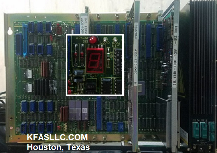
1 Normal operation in progress
4
Bad ACP daughter board
Replace ACP daughter board
8 On first power up. Problem caused by clock, custom LSI, CPU, BAC, or master PCB
Replace the appropriate board (master PCB)
BLANK (LED Not lit)
Power supply problem