![]()
![]()
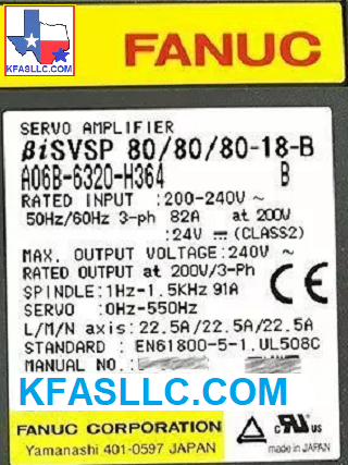
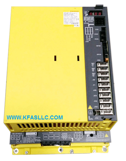
A06B-6320-H364 or A06B6320H364
SERVO/SPINDLE AMP BiSVSP-B 80/80/80-18-B
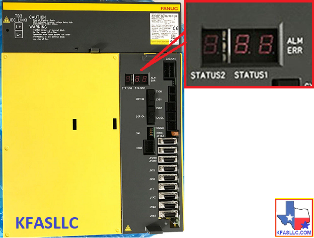
A06B-6320-H364 Series has two LED status indicators.
Alarm Code Description
Status 1
01 Motor overheat
02 Excessive speed deviation
03
DC link fuse is blown
04 Open phase in the converter
main power supply
6, 06 Temperature sensor disconnected
7, 07 Excessive speed
9, 09 Main circuit overload/IPM overheat
11 Converter: DC link overvoltage
12 IPM alarm
18 Program sum check error
19 Excessive offset of the phase
U current detection circuit
20 Excessive offset of the phase
V current detection circuit
21 Position sensor polarity setting
is incorrect
24 Serial transfer data error
27 Position coder disconnected
29 Short-period overload
30 Overcurrent in the converter input
circuit
31 Motor lock alarm
32 Serial communication LSI RAM
error
33 Converter: DC link precharge
failure
34 Parameter data out of the
allowable
range
35 Gear ratio parameter error
36 Error counter overflow
37 Speed detector parameter error
41 Position coder one-rotation signal
detection error
42 Position coder one-rotation signal
not detected
46 Position sensor one-rotation signal
detection error during thread cutting
47 Position coder signal error
50 Excessive speed command calculation value
during spindle synchronization
51 Converter: DC link undervoltage
52 ITP signal error I
53 ITP signal error II
54 Current overload alarm
58 Converter: main circuit overload
73 Motor sensor disconnected
75 CRC test alarm
79 Abnormal initial test operation
81 Motor sensor one-rotation signal
detection error
82 Motor sensor one-rotation signal
not detected
83 Motor sensor signal error
84 Spindle sensor disconnected
85 Spindle sensor one-rotation signal
detection error
86 Spindle sensor one-rotation signal
not detected
87 Spindle sensor signal error
A, A1, A2 Program ROM error
b0 Communication error between
amplifier and module
b1 Converter: control power supply
low voltage
C0, C1, C2 Communication data alarm
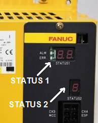
STATUS 2
Alarm
Description
2 Inverter: control power supply
undervoltage
5
Inverter: DC link undervoltage
b Inverter: motor current alarm (L axis)
C
Inverter: motor current alarm (M axis)
d Inverter: motor current alarm (N axis)
8. Inverter: IPM alarm (L axis)
9. Inverter: IPM alarm (M axis)
A. Inverter: IPM alarm (N axis)
F
Inverter: radiator cooling fan stopped
6 Inverter: overheat
P Amplifier and module
communication error
U FSSB communication error (COP10B)
A06B-6320-H332,
A06B-6320-H333, A06B-6320-H343
A06B-6320-H244