
![]()
![]()
![]()
![]()
![]()
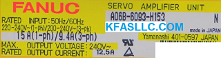
A06B-6093-H153 A06B6093H153 SVU-40
I/O Link Interface Type
Rated Input: 50Hz/ 60Hz
Single Phase: 220-240VAC, 15A
3-Phase: 200-240VAC, 9.4A
Rated Output: 240V, 12.5A
A16B–3200-0290 and A20B2100–0184
A06B-6093-H153 is
commonly used with Fanuc motor α4/4000i (40A), α8/3000i
(40A), αC22/2000i (40A)
Related Manuals
β series
Motor Descriptions (B–65232EN)
β series Maintenance Manual
I/O Link Option (B–65245EN)
Beta Servo Setting Information and Alarms
When Beta Servo unit with I/O Link is used, related
parameters must be set (and re-set upon the replacement of the amplifier) under
the Power Motion Manager (PMM) screen. For the power motion manager functions to run properly, it is necessary to set the
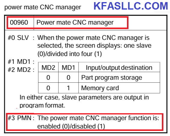
parameter 960 as follows on CNC parameter screen.
Parameter P960
(1) Bit 0 (SLV) (screen display)
0 : One slave per screen
1 : Four slaves per screen
(2) Bits 1 and 2 (MD1 and MD2) (data input/output destinations)
Bit2 Bit1
MD2 MD1
0 0 CNC memory (NOTE)
0 0 Memory card
(3) Bit 3 (PMM) (whether to disable the PMM)
0 : Enable
1 : Disable
It is required to backup and restore Power Mate CNC Manager parameters to Beta required when replacing a Beta drive.
1. Set NC PRM 960.3 (PMN) = 0 (Enables PMM function).
2. Select where parameters are to be saved (to save to memory card on i series controls make PRM 960.2
(MD2) = 0 and PRM 960.1 (MD1) = 1, to save as a part program make PRM 960.1 = 0).
3. Set parameter 8760 to the program number you want the parameters to be stored as.
4. Press the SYSTEM button then the RIGHT CHAPTER button until the Power Motion Manager screen is displayed.
5. Press the SYSTEM soft key.
6. Press the PARAM soft key.
7. Press the OPRT soft key.
8. Press the RIGHT CHAPTER button. READ and PUNCH soft keys will be displayed.
9. Select EDIT mode.
10.To save parameters from Beta drive to CNC press the READ soft key, press the ALL soft key then the EXEC soft key.
11.To restore the parameters from the CNC to the Beta drive press the PUNCH soft key, press the ALL soft key, then the EXEC soft key.
Controlled–axis parameter: 000
Coordinate system and stroke limit parameters
001, 068, 140 to 145, 147, 154 to 165, 170
Feedrate parameters
021, 040, 041, 043 to 050, 054, 061
Acceleration/deceleration parameters
002, 055 to 060
Input/output signal parameters
003 to 005, 020, 022, 023, 029, 062, 063, 148 to 152, 166 to 169
Servo parameters
010 to 014, 016, 030 to 032, 070 to 075, 078 to 092, 100 to 111, 116, 135, 136, 180 to 182


![]() © Copyright
KFASLLC Houston, Texas, USA
© Copyright
KFASLLC Houston, Texas, USA