


KFAS: Fanuc CNC Parts, Service, & Repair
Phone: (281) 769-2671F
E-mail: service@kfasllc.com
Fanuc 16/ 18/ 21 Data Download/ Backup
Step 1: Set up your Personal Computer (PC) or laptop to receive data.
(click here for information on RS232 setup)
Step 2: Punch out NC Parameters as follow
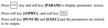
Select EDIT mode.
Press "SYSTEM" key then press soft key [PARAM]
to display parameter screen.
Press soft key [(OPRT)], and soft key [=>].
Press soft key [PUNCH] and [EXEC], and the parameters are started to be
output.
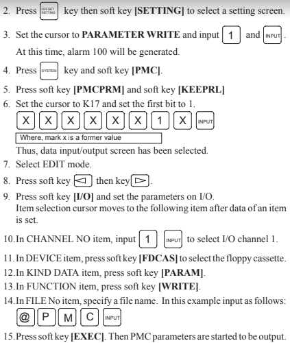
Step 3: Punch out PMC Parameters as follow
Press "SYSTEM" key then press soft key [PMC].
Press soft key [PMCPRM], and soft key [KEEPRL].
Set Keeprelay K17 bit#1 = 1.
Press soft key [PUNCH] and [EXEC], and the parameters are started to be
output.
Select EDIT mode.
Press soft key [<=] then key [=>]
Press soft key [I/O] and set the parameters on I/O.
Set CHANNEL NO = 1.
Set DEVICE = FDCAS.
Set DATA KIND = [PARAM].
Set FUNCTION = [WRITE]
Press softkey [EXEC] to start output.
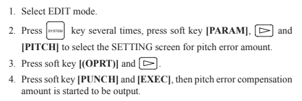
Step 4: Punch out Pitch Error as follow
Press "SYSTEM" key several time, then press soft key [PARAM], [=>]
and [PITCH].
Press soft key [OPRT] and [=>].
Press soft key [PUNCH] and [EXEC].
Make sure parameter no. 10 bit#4 = 0 (unprotect programs 9000 ~ 9999)
Select EDIT mode.
Select PROGRAM Memory screen.
Key in “O-9999”.
Press OUTPUT START.
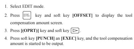
Step 5: Punch out Offsets as follow
Select EDIT mode.
Press [OFFSET/SETTING] key then [OFFSET] soft key.
Press OUTPUT START.
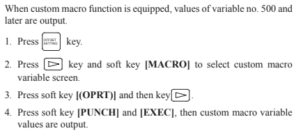
Step 6: Punch out Macro Variables as follow
Macro variables (#500 to #999) can be output.
Select EDIT mode.
Press [OFFSET/SETTING] key.
Press [=>] key and softkey [MACRO]
Press soft key [OPRT] and then [=>] key.
Press soft key [PUNCH] and [EXEC], then variables are output.
Fanuc
0 Data
Upload/
Restore
Step 1: If control is generating System Errors such as "Alarm 910 Ram Parity" or
"Alarm 911 Ram Parity", control memory must be first initialized.
Parity Alarm is usually caused by low memory backup battery.
(click here to view more information on memory backup battery replacement procedure)
Step 2: Initialized/clear memory by press and holding "RESET" & "DELETE" keys
simultaneously while powering ON the control.
Step 3: Control should power up to Alarm screen and it should show several alarms including
Alarm 100: Parameter Write enabled (PWE)
417: X Axis Digital Parameters
427: Y Axis (for milling machines) Z Axis (for lathes) etc.
Step 4: Push in E-Stop (Emergency Stop) button. Press "PARAM/DGNOS" key once to go to parameter screen.
Press "Page Down" key to go down to Parameter 38. Set parameter number 38 according to your backup list.
Alarm 000 Power off alarm may generate causing the control to switch to alarm screen. Press "PARAM/DGNOS" to return to paramter screen.
Page down to Parameter number 900 (you can also press "No." key then type in "900" then input to skip to parameter number 900.
Set parameter 900 to approximately about parameter 932 according to the backup list. When certain parameter 900 area data is set, control will generate a
warning message of something to the effect saying: press "Del" (Delete key) or "CAN" (cancel key) to continue. Press "DELETE" key and continue setting
900 series parameters according to the list.
Step 5: Turn power OFF and then back one after about one minute. Control should come on and show alarm screen still with several alarm previously mentioned.
If parameter backup is available on computer, setup the RS232 parameters on the control
Step 6: Input NC parameters as follow:
Select EDIT mode.
Select PARAMETER screen.
Press "INPUT" while holding "EOB" (End of block) key.
*Note: INPUT will flash in the lower right-hand corner and NC parameters will be input.
Alarm 000 Please turn power off message will appear once parameters are loaded. Power OFF/ON.
Step 7: Input PMC Parameters as follow:
Select EDIT mode.
Select DGN screen.
Hold EOB and press INPUT.
Step 8: Input NC Programs as follow:
Select EDIT mode.
Select PROGRAM Memory screen.
Verify Program Protect Key is OFF.
Press INPUT.
Step 9: Input Offsets as follow:
Select EDIT mode.
Select PROGRAM Memory screen.
Verify Memory Protect Key is OFF.
Press INPUT.
Run this program to write data to OFFSET screen.


 © Copyright 2024 KFASLLC Houston, Texas, USA