

Fanuc A16B-1212-0100 A16B12120100
The FANUC A16B-1212-0100 Power Supply is commonly used in Fanuc controls
such as 0MC and 0TC.
SAME DAY SHIPPING: IF ORDERED BY 3PM CENTRAL TIME
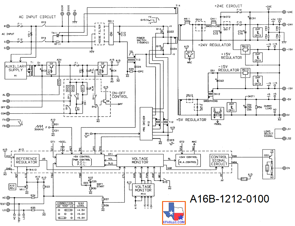
A16B-1212-0100 utilizes following fuses
F11/F12: Daito HP50
F13: Daito SMP32
F14: Daito MP75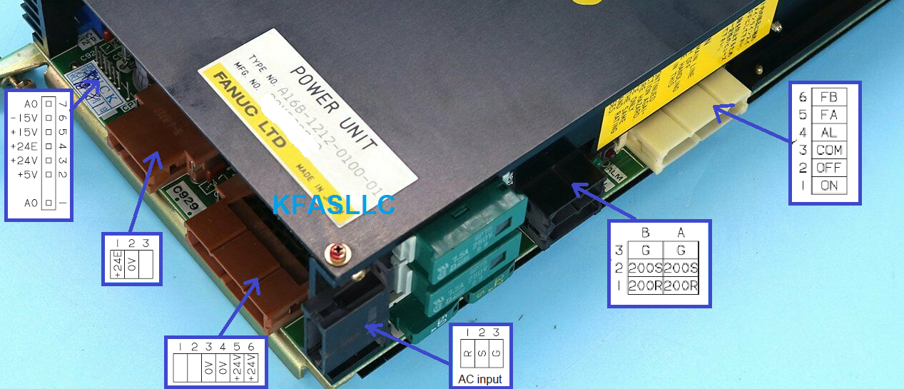
A16B-1212-0100 Connection Diagram
FANUC A16B-1212-0100 Power Supply is In Stock at KFASLLC for same day shipping.
RECONDITIONED AND TESTED
SAME DAY SHIPPING: IF ORDERED BY 3PM CENTRAL TIME
$825 ($175
Exchange Credit Available) ![]()
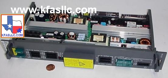
Fanuc
A16B-1212-0100 Power Supply Unit (PSU) is made specifically for GE FANUC and
FANUC CNC Controls including FANUC 0MC, FANUC OTC, FANUC O-C, FANUC 0MF, FANUC
0TF control series which
are used on thousands of CNC machine tools in machining industries.
The
Fanuc A16B-1212-0100 is designed to be easy to mount and dismount since it is
connected directly to the master printed–circuit board.
All
its AC inputs and DC outputs are securely connected via connectors rather than
screw terminals.
The
Fanuc A16B-1212-0100 power supply unit has a built–in input unit function and
it is not necessary to prepare a separate relay or input unit for switching the
AC input on and off.
The
AC input can be connected directly to the power supply unit.
The
unit also has an AC service outlet, which is switched on and off simultaneously
with the power supply unit.
This
AC service outlet can be used to supply power to a unit such as a fan motor.
Input/output connectors of A16B-1212-0100
CP1: 200/220/230/240 VAC input
CP2: 200/220/230/240 VAC output
(switched on and off simultaneously with the power supply unit)
CP3: Power on/off switch contact signal input
External alarm signal input
Alarm signal input
CP12: Supply of +5 V, +15 V, –15 V, +24 V, and +24E to the master PCB
EN signal output
CP14: Reserved for future use
CP15: +24V supply for the 9” monochrome CRT/MDI unit (for Series 0)
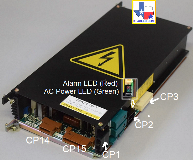
Descriptions of the input/output signals and display LEDs
1. AC power supply display LED (green)
When an AC power source is connected to the power supply unit,
the LED lights regardless of whether the unit is on or off.
2. Alarm display LED (red)
If the power supply unit is switched off because of an alarm
condition due to a failure such as an output error, the alarm
display LED lights and remains on until the alarm condition is
cleared by pressing the OFF switch or shutting down the AC
power supply.
3. ENABLE signal EN (output)
This TTL level signal indicates that all DC outputs are normal.
It becomes low if an output failure is detected in any circuit.


 ©
Copyright 2024 KFASLLC Houston, Texas, USA
©
Copyright 2024 KFASLLC Houston, Texas, USA