

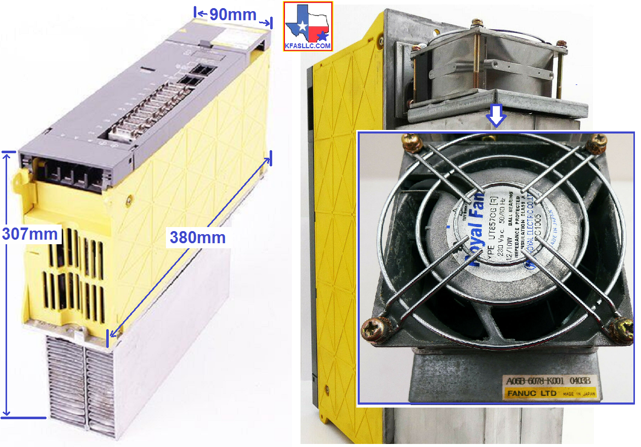
A06B-6078-H311 SPM-11
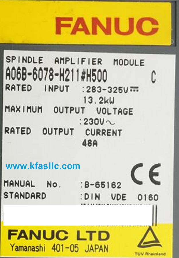
A06B-6078-H311#H500

SAME DAY SHIPPING: IF ORDERED BY 3PM CENTRAL TIME
$2,900 ($700
Exchange Credit Available) ![]()
Rated INPUT: 283-325VDC 13.2kW
Maximum OUTPUT: 230VAC 48A
Spindle Amplifier Module A06B-6078-H311#H500 is used with spindle motor Alpha6, Alpha8, AlphaP8 and AlphaP12
A06B-6078-H311 is commonly used in Star CNC and Citizen CNC machines.
Related technical information View Picture
A06B-6078-H311 Alarms Meaning and action to be taken
Alarm
Fault
– Not Ready(Not an alarm)
0
Control Ready(Not an alarm)
1 Motor overheat
2 Excessive Speed Error
3 Fuse on DC Link Blown(SPM is faulty)
4 Input Fuse/Power Fault(PSM is faulty)
5 Power Supply Fuse Blown
7 Overspeed
8 High Voltage Power Input
9 Overheat Main CIrcuit(SPM is faulty)
10 Low Voltage Input Power(Check input power)
11 Overvoltage in Power Circuit(PSM is faulty)
12
Overcurrent in Power Circuit
13 Data Memory Fault CPU(SPM is
faulty)
15
SP Switch Control Alarm
16 RAM Fault(SPM is faulty)
18 Sumcheck Error PGM Data
19
EX Offset Current U
20
EX Offset Current V
24 Serial Transfer Error(normal
if CNC is OFF)
25 Serial Transfer Stop
26 Disconnect C Velocity Detect
27 Pulsecoder Disconnected
28 Disconnect C-Pos Detect
29 Short time overload
30 Overcurrent(PSM is faulty)
31 Motor Lock or V-Sig Lost
32 Ram Fault Serial LSI
33 Shortage Power Charge(PSM is faulty)
34 Parameter Setting Error
35 Ex Setting Gear Ratio
36 Overflow Error Counter
37 Speed Detect Par. Error
39 1-Rot Cs Signal Detect
40 No 1 Rot Cs Signal Detect
41 1-Rot Position Coder Error
42 No 1 Rot. Position Coder Detect
43 Disconnect PC for Dif SP Mod
44 Control Circuit (AD) Error
46 Screw 1-Rot Position Coder Alarm
47 Position Coder Signal Abnormal
49 High Conv. Diff. Speed
50 Spindle Control Over Speed
51 Low Voltage DC Link(PSM is faulty)
52 ITP Signal Abnormal 1
53 ITP Signal Abnormal 2
56 Inner Cooling Fan Stop
57 Ex Deceleration Power
58 Overload in PSM(PSM is faulty)
59 Cooling Fan Stopped in PSM(PSM is faulty)
66 Communication Alarm between Spindle and Amplifier
69 Safety Speed Exceeded
70 Abnormal Axis Data
71 Abnormal Safety Parameter
72 Motor Speed Mismatch
73 Motor Sensor Disconnected
74 CPU Test Alarm
75 CRC Test Alarm
76 Safety Function Not Executed
77 Axis Number Mismatch
78 Safety Parameter Mismatch
79 Abnormal Initial Test Operation
81 Motor Sensor one-rotation signal detection error
82 Motor Sensor one-rotation signal not detected
83 Motor Sensor Signal Error
84 Spindle Sensor Disconnected
85 Spindle Sensor one-rotation signal detection error
86 Spindle Sensor one-rotation signal not detected
87 Spindle Sensor Signal Error
88 Cooling Fan on the radiator stopped(SPM is faulty)
A06B-6078-H311 Alarm 12 and Alarm 03
Troubleshooting Steps
(1) Power off the machine. Remove the power line wires from the spindle
amplifier terminals, and be sure to place them so that there is no chance
or shorting out something in the electrical cabinet. Power ON the machine/
control and command the spindle.
If Alarm 12 occurs, go to (3). If not, go to (2).
(2) Check for insulation between PE and each of the removed power wires U, V,
and W. Good/ acceptable insulation is in the order of several HUNDRED MEGA
OHMS or higher.
If not, disconnect the power wires from the motor. Then check for
insulation again between PE and each of the U, V, and W terminals on the motor
itself. If there is a short circuit between PE and U, V, or W of the
motor, replace the motor.
If motor insulation is tested good, replace the motor power wires.
Related Part NumbersKFASLLC kfasllc.com
A16B-2202-0682
A20B-2901-0851 (qty 3)
A16B-2202-0434


 © Copyright 2024 KFASLLC Houston, Texas, USA